
The first integrated bench tests
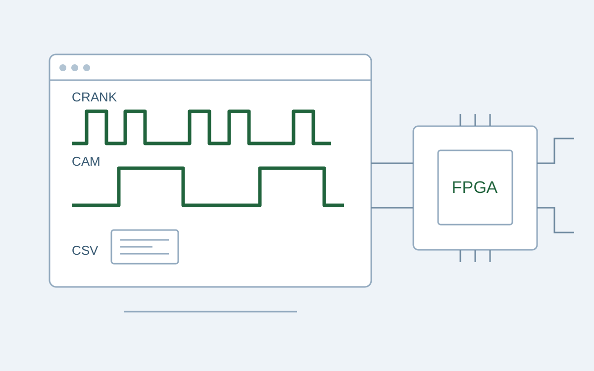
We took an FPGA test-bench prototype through its first integrated tests on a Digilent Arty A7-100T. From a browser, we can load a trigger-wheel profile, reproduce crankshaft and camshaft sensor signals, and observe how the analyser reconstructs speed, position and phase.
With an emulated 60-2 wheel at 20,000 rpm, we verified a pulse for every 0.01° of rotation on the board, equivalent to around 12 million pulses per second. This pulse grid describes the prototype’s angular reference; qualifying the system’s accuracy requires the corresponding measurements.
Long sequences with precise timing
The bench needs to repeat sequences long enough to represent different conditions while maintaining precise edge timing as the processor handles the network. We assigned configuration and telemetry to MicroBlaze with FreeRTOS and signal timing to FPGA logic running at 100 MHz.
Sequences are stored in DDR3L as intervals between transitions. Two independent DMA engines feed the sequencers a few samples ahead, reducing the use of internal FPGA memory.
Testing showed that crank and cam needed to complete their loops at different times. We made their periods independent and verified playback on the board with an 80 ms crank period and a 100 ms cam period.
From a CSV file to a repeatable test
After initial bare-metal checks of memory and peripherals, we moved the web server to FreeRTOS. The interface can load, display, edit and save CSV profiles or create one from a template.
Pages and profiles are stored in a littlefs filesystem on Quad-SPI flash. We verified that a malformed CSV is rejected while the last valid profile remains available. Status, measurements and logs reach the browser through Server-Sent Events on a connection that stays open during the test.
From missing teeth to angular position
The analyser’s functional reference is the eTPU library described in NXP AN4907 — Engine Control eTPU Library. We implemented two VHDL state machines: CRANK recognises the two-missing-tooth interval and tracks the wheel; SYNC uses the cam signal to distinguish the two revolutions of the engine cycle.
The analyser can receive signals from the internal emulator or the board connectors. With the internal emulator, we verified lock and phase validity at 600, 3,000 and 20,000 rpm.
At 20,000 rpm, the integrated FPGA logic analyser measured angular pulses 40 ns wide and two programmable logic markers 10 µs wide, starting at 15° and 25° respectively.
Comparing tests with the same profile
A saved profile allows the same sequence to be replayed and the analyser’s behaviour to be compared after a change. Test engineers can reuse the inputs and connect browser observations to internal logic-analyser captures.
This gives the customer a repeatable basis for discussing a configuration and documenting observations from the prototype. The work is part of our AI-assisted engineering approach.